Many electronic generations ago, during the 1970s, high-speed I/O copper connector popular types included coaxial BNC, pin-and-socket D-subminiature, and even a bit later the IDC Delta-ribbon varieties. Many cable assemblies were hand terminated by highly skilled manufacturing assemblers and technicians. In those days, accurate hand tools helped to generate a reasonable yield and rework level. Now, in mid-2016, automated red, green and blue lasers are used to weld tiny twin-axial wire conductors to contacts and even to PCB pads. Lasers also trim shields, dielectrics, conductors and cable jackets. In this two-part blog, I will address some old and new high-speed copper wire termination trends and issues relative to different process equipment and methods.
Coaxial solid conductor wire is inserted into a hollow metal cylinder within the backside of a precision-tooled BNC (Bayonet Neill–Concelman connector), leaving a thin gap. With a soldering iron held against the outer cylinder near the solder access side hole, an operator feeds solder into a small side hole until neatly filled.

Traditionally, high-speed D-subminiature pin and socket contacts have been mostly used with solder cup termination contacts that require neatly soldered fillets to maintain good SI functioning. Some lower speed I/O D-subminiature connector contacts have been crimp type, lower cost stamped contacts. The crimped wire and contact deformation were controlled in a tight range but still were not symmetrical enough for some higher speed I/O signaling. These early high-speed cable assembly types were used externally and within analog precision test and measurement equipment and later with digital single-ended parallel I/O interface cabling and active equipment. This hot iron method of direct solder processing is too variable and expensive to even semi-automate and the machined connector components were too expensive and too large for many subsequent newer generation applications/products. Some highly fixtured wave soldering beds were used with moderate success, especially for paddleboard type plugs and various cables. Still some of these simple, symmetrical BNC, pin-and-socket contacts have very good signal integrity design even with the variable soldered hole feature.

During the 1980s, IDC termination became popular as it was now possible to produce mass termination of dozens of wires at once with efficient semi-automatic tooling. The slight compression of the wire conductor by the IDC contact provided a gas-tight fit, reliable high-speed copper wire termination and met most signal integrity requirements.
Twisted pair solid wire conductors can easily be nicked or micro-cut during wire preparation and termination processing. A little jarring force later usually further cleaves across the wire conductor and it breaks off, becoming an open circuit or a short. So stranded wire became useful for reliable IDC termination and cable flexibility.
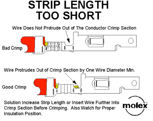
For inside the box and inside the rack, easy cable routing of early digital electronic equipment quickly became an issue. There was a switch to using mostly stranded TP wires in high-speed copper cables supporting single mode parallel I/O signaling. Maintaining evenly crimped contact tabs or flanges over small, finer stranded wires made up the resultant 28-30 AWG wire size terminations. This was a challenging process, as was producing crimp flanges over wire insulation for mechanical bend and tensile strengths. Very small trimmed fragment pieces and strands outboard the crimped flange zone known as “wire whiskers” caused performance pursuance and electrical failure modes. Those fallen small fragments also caused short other circuits on PCBs. The stripping of wire insulation and untwisting of wire pair ends increasingly became for maintaining accurate signaling performance.

Thus the focus during the 1990s was on developing and using newer reflow soldering termination methods that had better build yields, more automation and better SI performance and structure control. Contacts, via holes and PCB pads were covered with just the right amount of solder paste. The resultant soldered contact terminations became much more precise and repeatable. Several different reflow termination systems evolved. One of the first was the use of hot air knifes. Some air knifes were mechanized to move steadily over a set of connector contacts while other process lines had the set of contacts and wires move thru the fixed hot air zone.
In part 2 of this discussion, I’ll cover modern high-speed copper wire termination methods, such as hot bar solder and laser welding.
Leave a Reply
You must be logged in to post a comment.