By Josh Taylor, senior product manager at CABLExpress

Fiber optic cabling is widely used in data centers around the world, so it’s important to understand the basics. In fiber optic cables, data is transmitted through pulses of light and this digital signal is transmitted over a medium made of high-quality glass.
When considering fiber optics for your data center, the first thing to understand is the difference between single-mode and multi-mode fiber.
Single-mode fiber has a smaller core diameter and a higher bandwidth than multi-mode fiber. While it may seem that choosing a fiber with higher bandwidth would be a no-brainer, these single-mode transceivers are much more expensive than multi-mode transceivers. Due to budget restraints and the relatively short distances needed for active hardware links, multi-mode fiber is frequently used and performs well in the data center.
It is also important to understand the difference in core size diameters. In a data center environment, there are three to know:
• 9/125 single-mode
• 62.5/125 multi-mode
• 50/125 multi-mode
As shown in Figure 1, there are two main parts of the fiber—the core and the cladding. In the core, data is transmitted in the form of light pulses that are retained by the cladding. The cladding has a much lower refractive index, allowing it to keep the data inside the core. As an analogy, think of using bumpers while bowling. The core is the bowling lane and the bumpers are the cladding. If there were no cladding in place, most of the data would go in the gutter.
It is important to never mix fiber optic cores. For example, never plug a single-mode 9/125 cable into a multi-mode 50/125 cable. When cores are not matched properly, data transmissions will be lost.
While there are uses for both fiber optic and copper cabling in many data centers, fiber cabling has distinct benefits compared with copper in regard to transmission, attenuation and electromagnetic interference (EMI).
Transmission – The data transmitted through fiber optic cabling via light pulses comes from transceivers designed for this purpose. With copper cabling, information is transmitted with an analog signal. Because of this difference, fiber optic cabling allows for data transmission at greater volumes, faster speeds and longer distances.
Attenuation – Attenuation, or the reduction of signal strength, is important to consider when planning a cabling infrastructure. For example, think of how a voice carries. The farther away you are from someone, the harder it becomes to hear what is being said. Fiber optics have very low attenuation rates in comparison to analog copper signals.
EMI – Electromagnetic interference has traditionally been a challenge in data centers because of the large amount of power and cabling contained in a relatively small space. EMI is a disturbance that affects an electrical current, degrading signals and causing outages. Fiber optics are immune to EMI because of the nature of fiber transmission.
Maintain best practices
Bend radius – As we all know, when a cable is bent there is a reduction in the strength of that signal. This is no difference with fiber optic cables. The bend radius, or measurement of a curve, can determine how strong the data signal will flow. With fiber cabling, there are different specifications for bend radius varying by cable manufacturer and fiber type. There have been many improvements made in this area, including the development of “bend insensitive fiber,” commonly known as BIF. This fiber, widely used by cabling manufacturers, is less prone to the attenuation caused from bending. A good rule of thumb for determining bend radius during installation is that bend radius equals 10 times the outer diameter of the cable jacket. When in doubt, check with the manufacturer’s recommendations.
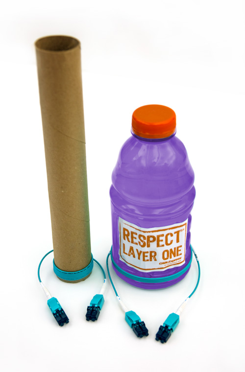
As shown in Figure 2, newer bend insensitive fiber has a much smaller bend radius. The BIF that is typically used today can bend around a paper towel roll and maintain its signal strength. Historically, fiber could only bend around the diameter of a 32-oz sports drink bottle.
Pulling fiber – In many cases, fiber cabling must run over long distances. Although fiber optic cabling assemblies are robust and sturdy, caution should be used when pulling. Never pull from the connectors; this is typically the weakest link in pulling strength. Always use a pulling sock to reduce strain on critical areas. Most manufacturers will have recommendations readily available based on their specifications.
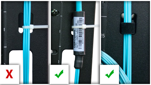
Tie-down points – Tie-down points are the areas where cables are affixed to patch panels or racks and cabinets to ensure they do not move around. Never use zip ties on fiber optic cabling unless there are specific designated areas on the cable to do so. Always use Velcro and never overtighten, as this can crack the fiber and cause failure; Figure 3 shows improper and proper ways to tie-down fiber.
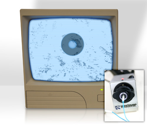
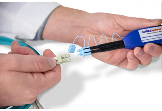 Avoid end face contamination – End face contamination is just like it sounds. Debris, dust and oil on your cabling end faces can wreak havoc on your network. This is one of the most common issues when dealing with fiber optic cabling failures. If there is anything on the end face of the cable, it will weaken the signal strength. It is always recommended to inspect, clean, inspect and then repeat as necessary, as shown in Figure 4.
 You first need to check the condition of the end face. If there is no contamination over the core or cladding, you can safely plug in the cable. If the end face is contaminated, it must be cleaned. When done cleaning, inspect again to ensure the contamination has been removed. If it still appears dirty, repeat the steps until the end face is free from contamination. Simple and cost-effective tools and cleaning kits are available that will help with this process.
As data rates continue to increase, the use of fiber optic cabling will gain greater prominence in many data center applications. A thorough understanding of the basics will help ensure a smooth transition process and serve as a strong foundation for the migration into fiber optics.
CABLExpress
www.cablexpress.com
Leave a Reply
You must be logged in to post a comment.